The water analogy
A
common analogy for electrical circuits is a closed hydraulic circuit. There are simple hydraulic devices corresponding to the three common passive electronic components: resistors, capacitors, and inductors. With effort you can imagine correspondences for more devices, but if you can do that, you can probably already understand the electronic devices directly.
Potential difference / emf / voltage
The analogy for potential difference is so direct that, to a physicist at least, you could use the same word whether you're talking about electrical or hydraulic circuits. Water at the top of a dam has a lot of (gravitational) potential energy compared to the water flowing in the river below. At the bottom of the dam wall this potential energy manifests as a high water
pressure, which a turbine can convert into mechanical work, as in a hydroelectric power station.
Just as you can feel water pressure when you try to block a hosepipe with a finger, you can also sometimes feel electric potential. On a dry day, after you take off a polyester jersey, you can feel the potential difference between your body and the garment: the static charge on the jersey attracts the fine hairs on your forearms, which bend slightly and give you that "electric" sensation.
We measure water pressure in pascal (Pa); typically in kilopascal (kPa), bar (multiples of atmospheric pressure), or pounds per square inch (psi) in some old-fashioned circles. Electrical "pressure", which we typically call "voltage", is in
volts (V). In modern hobby electronics, you're likely also to work in millivolts (mV) or even microvolts (µV), and only rarely kilovolts (kV).
Charge
Charge is the word we use for a quantity of electric charge. It tells you how much of the electric "stuff" you have: how many charge carriers (usually electrons, but also "holes" or even
ions). Where you might measure a quantity of fluid in liters (ℓ), gallons, cubic meters (m³), electric charge is in units of the
coulomb (C), which is a very large unit if you were to have that amount of charge isolated from the rest of the world. For example, the gate charge required to fully turn on a big power MOSFET might be several hundred nanocoulomb (nC).
Where charges are not isolated, however, it's easy to find loads of coulombs flowing around. One ampere of current (see below) is once coulomb passing a point in a circuit per second: If your electric power is at 230V, your kettle might experience 1500 coulomb passing through its heating element when you make tea for four! Moving electric stuff around is clearly easier than isolating it.
Current
Electrical current is the rate at which charge carriers (electrons, holes, or even ions, in an electrochemical cell) flow past a particular point in a circuit. The hydraulic analogy is also just a flow rate - of fluid particles (atoms or molecules, ultimately) instead of charge carriers.
You might see a hydraulic flow rate expressed as liters per second ℓ/s or m³/s; electric current is in
ampere (A) (usually only in high-power circuits), milliampere (mA), microampere (µA) or even smaller units. For example, the
1N4148 diode has a reverse leakage current measured in nanoampere (nA).
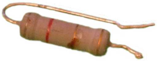
Resistors
 |
| An 8.2Ω power resistor |
A
resistor, unsurprisingly,
resists electrical current. The hydraulic analogy is a throttling valve; you probably have one (an adjustable one, too!) in your home. It's called a "tap". The greater the water inlet pressure, the faster the water flows into the sink. You can see (or feel!) the dependence on pressure when somebody opens another tap in the house: the flow rate decreases. When the washing machine opens its inlet valve, you can probably notice the difference quite plainly: you need to open the tap quite a bit further than normal if you want the same flow as you're used to.
And perhaps you've had the misfortune of having been in the shower when somebody flushed a toilet: scalding hot water rains onto you, as the drop in cold water pressure reduces the flow of cold water into the shower head, whilst hot water continues flowing at the same rate due to its supply from a pressure-reducing valve near the hot water tank.
When a resistor resists the current flowing through it, the electrical energy has to go somewhere. Resistors simply dissipate this energy as heat; sometimes a little too much:
 |
| A 22Ω power resistor |
You won't often see hydraulic resistance expressed as a quantity - mainly because flow rate is not linear in pressure difference.
I've covered linearity in another post. Electrical resistance, though, is measured in
ohms (Ω), more typically in kilohm (kΩ) or megohm (MΩ). Here is one with a fairly low resistance:
 |
| A 560Ω resistor |
Inductors
 |
| Air air-core solenoid |
An electrical inductor resists change in current; it
sets up a potential difference between its terminals that acts to maintain the instantaneous current. The inductor provides this emf by extracting energy from or storing it in the magnetic field surrounding its windings; this magnetic field is the source of energy required for the spark you can sometimes see when switching off an electric circuit.
 |
| Almost all of the magnetic field is inside the toroidal ferrite core |
Water hammer is a hydraulic phenomenon which parallels electrical inductance. A flowing liquid has inertia, which tends to resist changes in motion. If you have ever heard a light tap or even a loud bang when turning off a tap suddenly, you have witnessed the hydraulic equivalent of inductance: the inertia of the water in the pipes resists the sudden stop. The inertia continues to carry the water forward despite the closed tap; the water responds to the obstructed motion by compressing, which raises its pressure (a hydraulic form of back-emf). When the elevated pressure acts on the walls of the pipes, they expand slightly, or move. It is this expansion or motion that becomes audible as it couples into the air.
 |
| The ferrite core in this solenoid increases its inductance |
The unit of inductance is the henry (H), but that is an impractically large unit, so we rather use millihenry (mH) or microhenry (µH). There is no specific unit for hydraulic "inductance", but you could imagine the mass of fluid in the circuit to be somewhat analogous: more mass means bigger hammer.
Capacitors
 |
| 6800000pF at 250V - 5 for 5 zeroes after 68 |
If you live on a farm you probably know more about water reticulation than city slickers. You probably have a pump to deliver pressure to your home, but this pump can't run continuously: it would be wasteful, and it might burn out. Instead, you have an
accumulator that accepts high pressure water from the pump (when it runs) and supplies a steady high pressure flow to the household. An accumulator achieves this magic by having a rubber bladder separating the water in its vessel from a pocket of air. A one-way valve (a check valve - a hydraulic "diode") ensures that the pressurized water runs towards the household, and not back out the stationary pump.
 |
| Turn the screw to adjust the amount of air in the bladder |
City slickers too are able to see an analogue of a capacitor: a
water tower performs the same function in water reticulation as an accumulator. The only difference is that it uses Earth's gravity to pressurize the bottom of the column of stored water, instead of an air pocket.
Just as a hydraulic accumulator stores energy in the
compressed air inside the rubber bladder, a capacitor stores energy in the electric pressure - the potential difference - between its plates of conductive material. I've never seen the "capacitance" of a hydraulic accumulator stated, but it's obvious that there are big ones and small ones. If you insisted, you could state it in liters or cubic meters per bar: the more water you need to pump into the accumulator to produce a given pressure change, the higher its capacitance. To achieve a large hydraulic capacitance, you would need a physically large unit - you need space to put all the stored water.
 |
| An electrolytic capacitor that stores a lot of energy: 6.6 joule |
It is the same with electrical capacitance, whose unit is the
farad, although more commonly used multiples are the microfarad (µF) and picofarad (pF).
Capacitance determines how much charge you can store in a
capacitor for a given potential difference between its terminals. Again, to achieve a high capacitance, you need a physically large unit - space to put the conductive plates that store the charge. The colour bands on this capacitor indicate a capacitance of 4700pF:
 |
| Old-fashioned markings: colour bands |


